
LoRaWAN Architecture & Communication

LoRaWAN Architecture & Communication

Understand the complete LoRaWAN communication architecture in /IOTCONNECT™ — from physical radio signals to cloud dashboards. This section explains each layer, data flow direction, payload encoding / decoding, and how /IOTCONNECT™ bridges LoRaWAN with cloud applications.

End-to-End Architecture
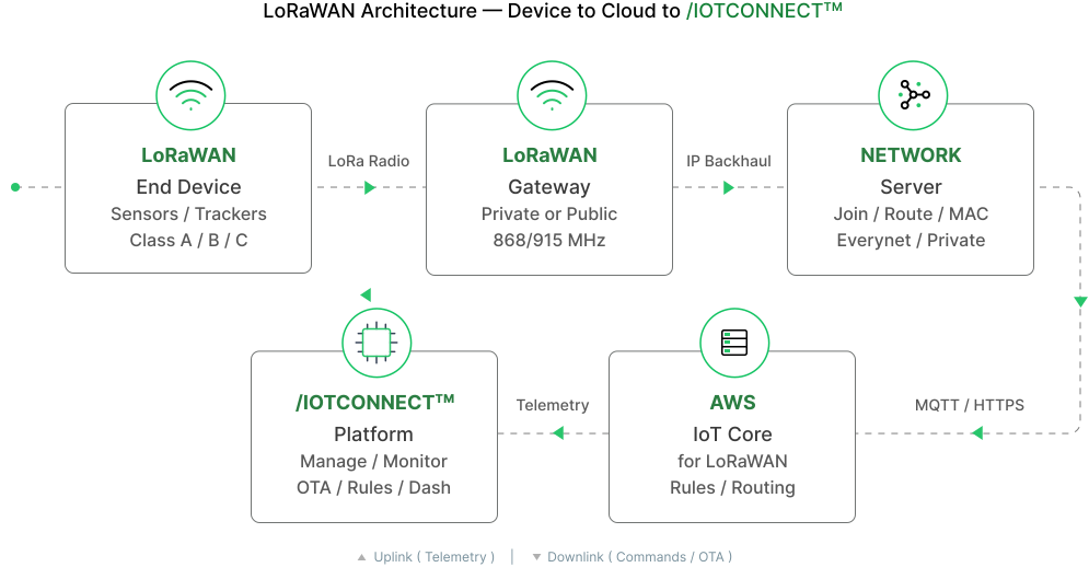
The complete LoRaWAN data path in /IOTCONNECT™ consists of five layers:

Layer Component Role
1. Device Layer LoRaWAN Sensor / Actuator Reads sensors, encodes data as binary payload, transmits via LoRa radio
2. Network Layer LoRaWAN Gateway Receives LoRa radio frames, forwards to cloud via IP backhaul (WiFi / Ethernet / LTE)
3. Cloud Network AWS IoT Wireless (LNS) LoRaWAN Network Server — handles join, MAC, deduplication, routing
4. Processing Layer /IOTCONNECT™ Lambda Decodes binary payload to JSON, maps to template attributes, routes to platform
5. Application Layer /IOTCONNECT™ Platform Stores telemetry, triggers rules, delivers to dashboards and APIs

Key Insight: Unlike standard IoT devices that connect directly via MQTT, LoRaWAN end devices generally communicate over LoRaWAN rather than directly using IP. They communicate solely via radio to a gateway, which provides the IP bridge to the cloud. This enables ultra-low-power operation (years on a single battery; depending on device, transmission interval, payload size, and environmental conditions) at the cost of limited bandwidth.

LoRa vs LoRaWAN

These terms are often confused. Here’s the distinction:

Aspect LoRa LoRaWAN
What it is Physical layer radio modulation Network protocol (MAC layer)
Analogy Like WiFi radio waves Like the TCP / IP protocol running over WiFi
Function Spreads signal over wide bandwidth for long range Manages device joining, addressing, encryption, MAC commands
Range Up to 15km (rural), 2-5km (urban) Same (uses LoRa as transport)
Frequency Sub-GHz: 868MHz (EU), 915MHz (US), 923MHz (AS) Same (defined by regional parameters)
Standardized by Semtech (proprietary modulation) LoRa Alliance (open standard)

Summary: LoRa = the radio. LoRaWAN = the protocol that uses the radio to create a managed network with security, addressing, and reliability.

Payload Encoding and Decoding

LoRaWAN devices send data in compact binary format (not JSON) to minimize airtime and power consumption. The /IOTCONNECT™ platform handles the conversion between binary and JSON automatically.

Why binary? A LoRaWAN payload is typically 1-51 bytes. Sending “temperature=23.5” as ASCII would waste 16 bytes. Sending the same as a 2-byte integer (235 = 0x00EB) uses only 2 bytes — saving 87% bandwidth and power.

Decoding (Uplink):

Device sends binary payload (e.g., 0x00EB 0x028A)

/IOTCONNECT™ Lambda decoder converts to JSON: {"Temperature": 23.5, "Humidity": 65.0}

JSON is mapped to template attributes and stored

Encoding (Downlink):

User enters command parameters in portal (e.g., interval=60)

/IOTCONNECT™ uses Bytes Command definition to encode: 0x01 0x3C

Binary payload is sent as downlink to the device

Decoder Types:

Decoder Description When to Use
Raw Data Default Passes raw hex payload — platform decodes Most common for standard sensors
Custom Decoder Custom Lambda logic from Key Vault Proprietary or complex encodings

Gateway Architecture

A LoRaWAN Gateway bridges the LoRa radio world with the IP network. It runs LoRa Basics Station software (minimum v2.0.4) which manages:

CUPS (Configuration and Update Server): Handles gateway credentials, configuration updates, and firmware management.

LNS (LoRaWAN Network Server): Handles LoRaWAN protocol — join, data routing, MAC commands, and scheduling downlinks.

Gateway provisioning requires:

Credential Source Purpose
Gateway Certificate (.cert.pem) Downloaded from /IOTCONNECT™ Mutual TLS authentication with LNS
Gateway Private Key (.private.key) Downloaded from /IOTCONNECT™ Proves gateway identity
CUPS URI Settings → Key Vault Gateway configuration endpoint
LNS URI Settings → Key Vault LoRaWAN data endpoint
Server Trust Certificate Downloaded from portal Validates server identity (Root CA)

Supported Hardware: Any gateway running LoRa Basics Station 2.0.4+. Tested with Dragino LPS8 Indoor Gateway.

Security Architecture

LoRaWAN security in /IOTCONNECT™ operates at multiple layers:

Layer Mechanism Protection
Radio (LoRa) AES-128 encryption (NwkSKey + AppSKey) Payload encrypted end-to-end from device to application
Network (Join) OTAA mutual authentication with AppKey Prevents unauthorized devices from joining
Transport (Gateway) Mutual TLS with X.509 certificates Secure gateway-to-cloud communication
Application AppSKey encryption (only application server can decrypt) Network operator cannot read payload data
Platform IAM roles, Lambda permissions, encrypted storage Secure processing and storage in /IOTCONNECT™

Key Management:

AppKey: Root key stored in device and /IOTCONNECT™. Used during OTAA to derive session keys.

NwkSKey: Network Session Key — used for MAC commands and frame integrity (MIC).

AppSKey: Application Session Key — used to encrypt / decrypt payload data.

ⓘ LIMITATIONS

Connection Status: /IOTCONNECT™ does not show live connected / disconnected status for LoRaWAN devices. Only last communication time is displayed.
Shadow / Twin: IoTConnect LoRaWAN devices currently do not support Shadow/Twin updates.
Message Rate: LoRaWAN has duty cycle limits (1% in EU868; Duty-cycle restrictions may apply depending on the regional frequency plan and applicable regulations). Devices typically send every 5-60 minutes; Transmission frequency depends on the device configuration and application requirements.
Payload Size: Maximum 51 bytes per uplink at SF12, up to 242 bytes at SF7. Plan payloads accordingly.